My shopping cart
Your cart is currently empty.
Continue ShoppingBy R&D
Published on January 5th, 2024
As an Amazon associate, we earn from qualifying purchases.
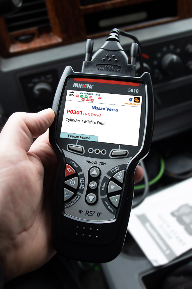
This article outlines the procedures to diagnose and confirm Diagnostic Trouble Code (DTC) P0301 on a 2014-2019 Nissan Versa and to replace the Ignition Coil to resolve the issue.
In cases where the Malfunction Indicator Lamp (MIL) on your vehicle’s dashboard is illuminated and the Engine Control Module (ECM) has stored DTC P0301 (Cylinder 1 Misfire Fault), it indicates the ECM has detected that the engine speed fluctuates through the Crankshaft Position Sensor (CKP) signal when the misfire occurs. A common cause of this DTC is the ignition coil.
The ignition coil plays a vital role in the efficient and reliable operation of an internal combustion engine. It acts as a transformer, converting the low voltage power from the battery into the high voltage required to create the spark needed to ignite the air/fuel mixture in the engine's combustion chamber.
To correct this issue, inspect the vehicle’s ignition system and replace the ignition coil as needed.
Symptoms of DTC P0301 include:
Possible causes of this fault are:
When DTC P0301 is present on a 2014-2019 Nissan Versa, replacing the ignition coil may resolve the issue.
| Table header 0 | Step Time required (hour) Sections Cautions | 3 1 4 0 |
|---|---|---|
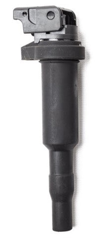
| Model | Part number | Part name |
| Nissan Versa L4-1.6L | 224485RB0A | Ignition Coil |
(This image is for illustrative purposes only and may not match the actual part number)
Find the perfect scanner in 1 minute
During your initial inspection, check for torn inlet boots, missing/broken vacuum tees, and disconnected wire harnesses. Check that Ignition Coil(s) fit tightly on Spark Plugs, and properly into the cylinder head. Ensure Ignition Coil harness connector(s) properly fit into connector/holders to prevent issues.
With the engine idling, you may try spraying a fine mist of water across the wires and coil, looking for arcing and, or RPM change. Refer to the Vehicle Emissions Warranty Manual for time and mileage coverage of emissions-related fault(s). For additional information, refer to the Service Manual or applicable Technical Service Bulletin (TSB).
Turn vehicle ignition to the Key ON Engine OFF (KOEO) position. Use a Scan Tool to access the Powertrain/Active Test/Power Balance. Set the parking brake. Start and idle the engine. Perform Active Test mode for each injector and observe the engine speed in Live Data (LD).
If the engine speed drops momentarily, check for intermittent loose connections. Perform Repair Validation.
If the engine speed does not drop momentarily, go to step 2.
Disconnect the ignition coil harness connector. Using a Digital Multimeter (DMM), measure the voltage between Pin 3 (Yellow) and the ground.
If battery voltage is not present, repair or replace the harness or connectors. Perform Repair Validation.
If battery voltage is present, go to step 3.
Remove the ignition coil and spark plug from the cylinder identified in the DTC. Connect the spark plug and harness connector to the ignition coil. Fix the ignition coil with a gap of 0.52–0.66 in (13 –17 mm) between the edge of the spark plug and a grounded metal portion. Crank the engine for about 3 seconds, and check whether a spark is generated between the spark plug and the grounded metal portion.

Check spark is generated
If a spark is not generated, replace the ignition coil with the power transistor. Perform Repair Validation.
If a spark is generated, go to step 4.
Remove the spark plug and inspect it. The spark gap should be 1.1 mm (0.043 in). Perform a quick compression check to determine if the compression is the root cause. Then, follow the appropriate diagnostic procedure and repair as specified. If compression, spark plug, and gap are good, move the ignition coil and spark plug to another cylinder. Perform Repair Validation.
If a DTC is set for the cylinder where the spark plug was moved, replace the spark plug. Perform Repair Validation.
If the same DTC is set, perform Repair Validation.
Step 1 – Disconnect the battery negative cable.
Step 2 – Remove the intake manifold.
Step 3 – Remove the ignition coil.
Installation is accomplished in the reverse order of removal.
Step 1: Clear DTC(s) and Freeze Frame (FF) information.
Step 2: Perform the KOEO and Key ON Engine RUNNING (KOER) tests or follow the On-Board Diagnostics (OBD2) drive cycle requirements for the fault area.
Step 3: An optional method to validate the repair would be to operate the vehicle within the conditions recorded in the FF data.
Step 4: Check for pending or stored DTC(s). If none is found, the repair is complete.
Hop in the discussion board on our community site!
It's a place where we help each other answer questions. Like Reddit but for automotive lovers.
SUBSCRIBE & GET ACCESS TO LIMITED-TIME OFFERS